| Full Topic |

| Joined: | Wednesday Aug 9th, 2006 |
| Location: | Singapore |
| Posts: | 3493 |
| Status: |
Offline
|
The minimum equipment required are
- Comfort CP9000 Controller including Metal enclosure and transformer
- Keypad one or more of KP03, KP04, KP05, KP06, KT03
- UCM/ETH03 or UCM/USB for programming with Comfigurator. The UCM is required to program Comfort but is not required for normal operation, and can be removed after programming. However a UCM/ETH03 allows remote proramming and access by Comfort iPad, iPhone, Android phone or tablet apps and is recommended to be included.
- Other UCMs (like KNX, Cbus, Zwave, GSM), Door Stations, SCS/RIO or Slave Expansions (optional)
Refer to the Hookup Diagram for the connection information
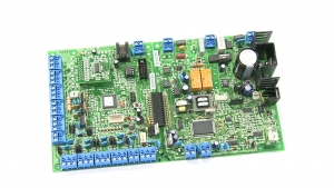
Enlarged illustration of the Comfort PCB:

Pluggable terminal blocks are used in Comfort so that the terminal blocks can be removed from the PCB without unscrewing wires, which is a great time-saver.
The Inputs Z1 to Z8 are normally connected to security sensors and magnetic contacts. Each pair of Inputs eg Z1 and Z1 has a common center connection. Each input has a jumper setting (JZ1 to JZ8) for No End of Line or Double end of line resistor. If the sensor does not have 2 end of line resistors (supplied in the accessory pack) then the JZ1 to JZ8 shunt should be plugged closer to the terminal blocks in the NO EOL position.
The optional LEM02B with additional 8 Inputs (0 Outputs) is plugged in to the CM9001 PCB on the LEM 10 way female connector
If the sensors are not connected at this time, the Zone Test Switch is a useful tool to simulate the inputs for testing. a ZTS is connected to a pair of inputs and has buttons to simulate the input. Each input can be set at Normally Open or Normally Closed state. Since alarm inputs are normally closed, the ZTS is very useful especially when testing inputs that are not connected or wired yet.

The alarm outputs (Siren, Strobe and Speaker) can be left unconnected.
OP1 to OP8 are the 8 Open-collector outputs. 2 adjacent Outputs have a common +12V terminal. When the output is turned on, the output terminal is pulled to a low voltage (near 1V). The Outputs can be connected to Relays RLY01,RLY02) or to Infrared Transmitters (IRM01, IR01W, IR03W in order to send Infrared signals to AV equipment or split unit Airconditioners. The outputs can be left unconnected if not used.
The Test Lamps are connected to a pair of outputs. This is a useful tool that allows testing of outputs

The Tamper Input on Comfort (TAMP and COM) must be shorted to prevent the Tamper alarm from being activated immediately on power on. This is normally connected to a Tamper switch.
The TEL IN terminal can be connected to the incoming telephone line. If not available, it can be left open, but take note that this will cause a "Phone Trouble " alarm to happen after 1 minute of power on.
The TEL OUT terminal can be connected to the house phones or left open at this stage
Connection to an external Siren/bellbox instructions can be seen here http://www.comfortforums.com/forum16/2288.html
The Transformer secondary is connected to the terminals marked "AC 14V"
The Back up battery (12V 7AH sealed lead acid) is required to provide backup power to Comfort in case of mains power failure.

The battery is connected to BATT+ and BATT- terminals using the battery cable.
The RED wire must be connected to the 12V terminal of the battery and the Black wire to the 0V (negative) terminal. Reverse connection will cause a short circuit and will cause excessive heating of the cable and damage to the battery

The battery need not be connected at this time. It can be connected after the system is tested.
The Comfort Installation Manuals has full instructions
There is a detailed Connection diagram which can be downloaded from http://www.cytech.biz/hookup_diagram.html
The Comfort Wiring Guide for additional information can be downloaded from http://www.cytech.biz/comfort_wiring_guide.html
Last edited on Friday Apr 7th, 2023 07:37 am by
| Close Window |