| Posted: Wednesday Jun 8th, 2011 11:47 am |
|
1st Post |
ident
Administrator

| Joined: | Wednesday Aug 9th, 2006 |
| Location: | Singapore |
| Posts: | 3493 |
| Status: |
Offline
|
back to top

|
The wiring diagram shows how to connect most Siren/Bellboxes to Comfort
The diagram is from the Comfort Installation Manual
SRN+ Siren (+) output has constant 12 volts to be connected to the Siren box.
SRN- Siren (-) output is normally floating, but pulled to ground to activate siren.
The Tamper terminals of the Siren/Bellbox can be connected in series with the Case tamper switches. Alternately the Siren/Bellbox tamper terminals can be connected to a spare zone input on Comfort which is programmed as a Tamper Zone Type.
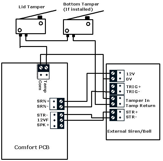
If the siren/bellbox sounds softly as soon as it is connected connect a pull-up resistor (1K-ohm) placing between the SRN+ and the SRN- 'terminal. If you wish to work on the siren/bellbox connections or open the control panel, you can prevent the system from causing a tamper alarm by entering Engineer Test Mode via Eng. Menu 8,6, 1 for on. Upon deselecting this option 8,6 ,0 for Off, the system will enter Security Check Mode and will report any faults through the keypad. Tamper Alarm means the Panel Tamper or Bellbox Tamper switch or Connections are open or incorrect.
Last edited on Saturday Dec 6th, 2014 05:53 am by slychiu
|
| Posted: Tuesday Jun 26th, 2012 04:23 pm |
|
2nd Post |
wexfordman
UCM Pi Users
| Joined: | Monday Jan 1st, 2007 |
| Location: | Cork, Ireland |
| Posts: | 546 |
| Status: |
Offline
|
back to top
|
Hi,
Any suggestions on why my external bell box strobe is working but no bell?
Regards
Eamon
|
| Posted: Wednesday Jun 27th, 2012 03:03 am |
|
3rd Post |
ident
Administrator
| Joined: | Wednesday Aug 9th, 2006 |
| Location: | Singapore |
| Posts: | 3493 |
| Status: |
Offline
|
back to top
|
The of the below possibilities
- The bellbox is not working
- the siren output is not working
- The connections are wrong for the bellbox you used
To check (2) get the alarm to activate and measure the voltage between SRN- and SRN+ using a multimeter. It should be 12V That means voltage is applied to the bell and one of the other 2 possibilties is true
|
| Posted: Tuesday Aug 28th, 2012 03:43 pm |
|
4th Post |
auredor
Member
| Joined: | Sunday Feb 19th, 2012 |
| Location: | |
| Posts: | 20 |
| Status: |
Offline
|
back to top
|
Hello,
I've a similar issue.
I've got a siren box that only need to be triggered to be enabled. The siren manages its own melody and includes a battery.
This siren is supply by a power of 14VDC. The trigger should be at 14VDC to keep the siren quiet and goes to 0VDC to enable the siren.
Unfortunately, using SRN+, SRN- and STR- doesn't provide enough voltage (12VDC max) to keep the siren disable. So today, I've to use a standard output of the Comfort in ON state with one wire not on the common and the second wire on the supply from the comfort to get 13VDC what is enough to keep it quiet. However I'had to manage this output "manually" and reprogram (enabling, disabling, siren duration...) the Comfort to get a similar behaviour than using directly the dedicated output. This is not perfect but it works. Obviousl I would prefer to do in a cleaner way because there is still some featues that I don't have resimulated. Any idea?
I though to use a relay with the 14VDC power supply transformer. But if the general power supply faild, it means that the siren will be enabled although there is no intrusion.
|
| Posted: Wednesday Aug 29th, 2012 02:12 am |
|
5th Post |
ident
Administrator
| Joined: | Wednesday Aug 9th, 2006 |
| Location: | Singapore |
| Posts: | 3493 |
| Status: |
Offline
|
back to top
|
It is not that the SRN does not supply enough 12V.
The SRN +/SRN- outputs will turn on 12V when the alarm triggers so it is the opposite of what you are trying to get.
If you want the reverse, ie the siren voltage to turn on when there is NO alarm, and voltage off when there is alarm, then go to Configuration > Modules a& Settings> and enable Siren Reverse then write to Comfort
|
| Posted: Wednesday Aug 29th, 2012 07:44 am |
|
6th Post |
auredor
Member
| Joined: | Sunday Feb 19th, 2012 |
| Location: | |
| Posts: | 20 |
| Status: |
Offline
|
back to top
|
I've changed this configuration but the voltage is not high enough (checked 12VDC with voltmeter) and the siren doesn't remain disable.
|
| Posted: Wednesday Aug 29th, 2012 12:42 pm |
|
7th Post |
ident
Administrator
| Joined: | Wednesday Aug 9th, 2006 |
| Location: | Singapore |
| Posts: | 3493 |
| Status: |
Offline
|
back to top
|
What exactly is the voltage when there is no alarm?
what is the voltage when there is an alarm?
|
| Posted: Wednesday Aug 29th, 2012 02:15 pm |
|
8th Post |
auredor
Member
| Joined: | Sunday Feb 19th, 2012 |
| Location: | |
| Posts: | 20 |
| Status: |
Offline
|
back to top
|
At 12VDC the siren is switched on
Above 13VDC the siren switches off.
|
| Posted: Thursday Aug 30th, 2012 01:48 am |
|
9th Post |
ident
Administrator
| Joined: | Wednesday Aug 9th, 2006 |
| Location: | Singapore |
| Posts: | 3493 |
| Status: |
Offline
|
back to top
|
If the siren switches off only above 13V that shows that there is something wrong with the siren, or it is not suitable for alarm systems which supply 12V
With the AC off, the alarm is powered by the battery until 11V
Last edited on Thursday Aug 30th, 2012 02:10 am by ident
|
| Posted: Friday Nov 30th, 2012 08:55 pm |
|
10th Post |
gimi
Member
| Joined: | Saturday Jun 2nd, 2012 |
| Location: | |
| Posts: | 15 |
| Status: |
Offline
|
back to top
|
Hello,
I purchased the GE AS6430 siren system which I want to connect to Confort but following the attached diagram, I am not sure the below connection are right:
Confort - AS630
SRN+ - 3
SRN- - 2
STR- - 1
12VF - ???
Thank you in advance for your support.
Mihai.Attachment: GE AS630 connection diagram.jpg (Downloaded 219 times)
|
| Posted: Saturday Dec 1st, 2012 12:25 am |
|
11th Post |
ident
Administrator
| Joined: | Wednesday Aug 9th, 2006 |
| Location: | Singapore |
| Posts: | 3493 |
| Status: |
Offline
|
back to top
|
what a complicated diagram
I would guess
SRN+ Open (it is also 12V supply)
SRN- - 2
STR- - 1
12VF - 3
COM - 4
|
| Posted: Saturday Dec 1st, 2012 03:35 pm |
|
12th Post |
gimi
Member
| Joined: | Saturday Jun 2nd, 2012 |
| Location: | |
| Posts: | 15 |
| Status: |
Offline
|
back to top
|
Thanks Ident,
Close guess but unfortunately as soon as I power on the alarm the siren starts buzzing! Just FYI, I do not use the Comfort tamper.
Mihai.
|
| Posted: Saturday Dec 1st, 2012 10:10 pm |
|
13th Post |
| Posted: Monday Dec 3rd, 2012 09:16 pm |
|
14th Post |
gimi
Member
| Joined: | Saturday Jun 2nd, 2012 |
| Location: | |
| Posts: | 15 |
| Status: |
Offline
|
back to top
|
Hi there,
Thanks for your involvement. Cutting the jumpers is not the same as connecting the cable to different outputs therefore I would like to ensure I cut the rights ones.
Just to check if I well understood the diagram. By cutting the J4 and J6 it means the siren will switch on when the input signal will switch from 12VDC to 0VDC, right? Just FYI, I do not use the siren internal battery thus the J3 is cut. Having the J3 already off it is not the J5 and J7 I have to cut? I expect GE to care of energy consumption and not keeping continuous 12VDC on the siren.
Cheers,
Mihai.
|
| Posted: Tuesday Dec 4th, 2012 11:38 am |
|
15th Post |
ident
Administrator
| Joined: | Wednesday Aug 9th, 2006 |
| Location: | Singapore |
| Posts: | 3493 |
| Status: |
Offline
|
back to top
|
Comfort wil pull down the Siren and Strobe Outputs to turn the respective device on, so wiredhome should be correct to say J4 and J6 should be cut
This should be regardless of whether you use the internal battery or not
If the internal battery is used, the siren will sound when the 12V voltage from Comfort is disconected. At least that is how I understand it
|
| Posted: Saturday Dec 8th, 2012 06:24 pm |
|
16th Post |
gimi
Member
| Joined: | Saturday Jun 2nd, 2012 |
| Location: | |
| Posts: | 15 |
| Status: |
Offline
|
back to top
|
Dear ident and wiredhome,
Thank you very much for your support. Unfortunately by cutting J4 and J6 I got the same behavior as before, as soon the power of the Comfort is on the siren and strobe are on and remains like this even after the security off message (thus Comfort doesn't send any alarm messages). FYI,the Comfort tamper is in loop as I do not use it. The GE siren 5 and 6 connectors are not connected. Should I try the J5 and J7 as I do not see other combination as long as the connections with the Comfort are OK?
Cheers,
Mihai.
|
| Posted: Sunday Dec 9th, 2012 02:29 am |
|
17th Post |
ident
Administrator
| Joined: | Wednesday Aug 9th, 2006 |
| Location: | Singapore |
| Posts: | 3493 |
| Status: |
Offline
|
back to top
|
No, I dont think J5 and J7 should be cut
Try Connecting a 1K resistor between the 12V and Siren and between 12V and Strobe terminals as shown in their diagram
|
| Posted: Tuesday Dec 18th, 2012 04:32 pm |
|
18th Post |
gimi
Member
| Joined: | Saturday Jun 2nd, 2012 |
| Location: | |
| Posts: | 15 |
| Status: |
Offline
|
back to top
|
Thanks! Adding the resistor solved my issue!
Strange enough for GE not to provide a resistor taking in consideration it is required.
Cheers,
Mihai.
|
| Posted: Wednesday Dec 19th, 2012 09:38 am |
|
19th Post |
wiredhome
Comfort Distributors

| Joined: | Thursday Apr 12th, 2007 |
| Location: | Dublin, Ireland |
| Posts: | 81 |
| Status: |
Offline
|
back to top
|
The resistors are provided with the GE Panels
|
| Posted: Sunday Mar 17th, 2013 08:04 pm |
|
20th Post |
sppooky
Member
| Joined: | Friday Dec 21st, 2012 |
| Location: | |
| Posts: | 11 |
| Status: |
Offline
|
back to top
|
Hi I wonder if anyone can help me. I'm just completing final installation of comfort alarm system and just got bellbox to connect. It's a Honeywell AG6 external sounder and strobe. Can anyone tell me where, on the comfort panel, I need to connect the following connections:-
TR- negative tamper return
V- negative supply
ST- negative strobe trigger
V+ positive supply
S- negative sounder trigger
Thanks
Rikki
|
| Posted: Monday Mar 18th, 2013 02:41 am |
|
21st Post |
ident
Administrator
| Joined: | Wednesday Aug 9th, 2006 |
| Location: | Singapore |
| Posts: | 3493 |
| Status: |
Offline
|
back to top
|
sppooky wrote:
TR- negative tamper return
V- negative supply
ST- negative strobe trigger
V+ positive supply
S- negative sounder trigger
TR- negative tamper return - to TAMP
V- negative supply - to COM
ST- negative strobe trigger - to STR-
V+ positive supply - to +12V
S- negative sounder trigger - to SRN-
|
| Posted: Saturday Mar 30th, 2013 08:03 pm |
|
22nd Post |
sppooky
Member
| Joined: | Friday Dec 21st, 2012 |
| Location: | |
| Posts: | 11 |
| Status: |
Offline
|
back to top
|
Hi thanks for the reply. When I opened the bell box the connections are slightly different to what was stated in the instructions. The 5 wired connections are
ST-
R-
SW-
V+
V-
Does R- go into tamp? What about SW-?
CheersLast edited on Saturday Mar 30th, 2013 08:05 pm by sppooky
|
| Posted: Sunday Mar 31st, 2013 02:38 am |
|
23rd Post |
ident
Administrator
| Joined: | Wednesday Aug 9th, 2006 |
| Location: | Singapore |
| Posts: | 3493 |
| Status: |
Offline
|
back to top
|
There must be some documentation to explain these labels otherwise you will have to do it by trial and error for R- and SW- for tamper and siren -ve
|
| Posted: Thursday Apr 4th, 2013 12:40 pm |
|
24th Post |
wiredhome
Comfort Distributors
| Joined: | Thursday Apr 12th, 2007 |
| Location: | Dublin, Ireland |
| Posts: | 81 |
| Status: |
Offline
|
back to top
|
i would think
st- strobe trigger
r- tamper return
sw- siren trigger or tamper switch neg
ve+ pos bell hold
ve- neg bell hold off
scan and post the instructions from the sirenor a photo of the connections and i can decipher them for you
|
| Posted: Tuesday Jul 16th, 2013 06:07 pm |
|
25th Post |
steefdebruijn
Member
| Joined: | Sunday Jul 29th, 2012 |
| Location: | Netherlands |
| Posts: | 28 |
| Status: |
Offline
|
back to top
|
Hi
Same question, different hardware. The aritech as271 has the following connections:
Tamper (2 connections)
12V
Siren-
Strobe-
How to connect to comfort?
I did the following, but cannot test yet because my house is not finished :-)
Tamper: dedicated alarm input, must program as tamper alarm
12V: srn+
Siren-: srn-
Strobe-: str-
But maybe the siren is a normal speaker and i should use the spk- and 12vf terminals...
Steef
|
| Posted: Wednesday Jul 17th, 2013 02:26 am |
|
26th Post |
ident
Administrator
| Joined: | Wednesday Aug 9th, 2006 |
| Location: | Singapore |
| Posts: | 3493 |
| Status: |
Offline
|
back to top
|
Your connection seem correct
Do not connect to the SPK terminals of Comfort. External bellboxes are not that way
|
| Posted: Saturday Sep 14th, 2013 05:59 pm |
|
27th Post |
ninotorres
Member
| Joined: | Tuesday Nov 10th, 2009 |
| Location: | |
| Posts: | 36 |
| Status: |
Offline
|
back to top
|
Anyone has experience in connecting an EDS AS240 siren to Cytech?
The only documentation I have is the one in the following URL:
http://www.unitech.com.tr/upload/KLAVUZ/EN/AS240_Eng.pdf
Attached is a picture of the only connections I can see in the SIren. My bet is:
PCM SRN+ ---> SIREN "+"
PCM SRN- ---> SIREN "-"
PCM STR- ---> SIREN "B"
Comfigurator settings are at default on the siren related settings.
I don't get any sound on Siren. I can't even see the status leds in the Siren blinking.
The siren has a battery module that I can be sure if it is only for backup or for normal operations. Is it possible that the bateries are depleted?
Thanks,
NinoAttachment: WP_20130914_004.jpg (Downloaded 69 times)
|
| Posted: Sunday Sep 15th, 2013 03:01 am |
|
28th Post |
ident
Administrator
| Joined: | Wednesday Aug 9th, 2006 |
| Location: | Singapore |
| Posts: | 3493 |
| Status: |
Offline
|
back to top
|
The photo does not match the connections on the manual
Photo has Tamp , + - B
Manual is SAB, + - S
You should ask them for the correct manual
The + and - should be from Comfort12V and COM, NOT SRN+ and -
Assuming the B terminal is siren trigger, this should be connected to SRN-
Attachment: siren.jpg (Downloaded 69 times) Last edited on Sunday Sep 15th, 2013 03:30 am by ident
|
|