Comfort Automation/ Security System Forums > Support > Comfort Installation and Programming Guide > Comfort Installation Instructions > Connecting Comfort - Quick Guide |
Comfort Automation/ Security System Forums > Support > Comfort Installation and Programming Guide > Comfort Installation Instructions > Connecting Comfort - Quick Guide |
| Moderated by: admin | Topic closed | |
| Author | Post | |||||||||
|---|---|---|---|---|---|---|---|---|---|---|
|
ident Administrator 
|
This is a short guide to connecting Comfort and other modules for the first time. This assumes that the setup and connection is done on the test bench prior to installation and the Comfort system is at default condition, ie has not been programmed yet. The minimum equipment required are
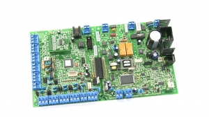 Refer to the Hookup Diagram for the connection information Enlarged illustration of the Comfort PCB:  Pluggable terminal blocks are used in Comfort so that the terminal blocks can be removed from the PCB without unscrewing wires, which is a great time-saver. The Inputs Z1 to Z8 are normally connected to security sensors and magnetic contacts. Each pair of Inputs eg Z1 and Z1 has a common center connection. Each input has a jumper setting (JZ1 to JZ8) for No End of Line or Double end of line resistor. If the sensor does not have 2 end of line resistors (supplied in the accessory pack) then the JZ1 to JZ8 shunt should be plugged closer to the terminal blocks in the NO EOL position. The optional LEM02B with additional 8 Inputs (0 Outputs) is plugged in to the CM9001 PCB on the LEM 10 way female connector If the sensors are not connected at this time, the Zone Test Switch is a useful tool to simulate the inputs for testing. a ZTS is connected to a pair of inputs and has buttons to simulate the input. Each input can be set at Normally Open or Normally Closed state. Since alarm inputs are normally closed, the ZTS is very useful especially when testing inputs that are not connected or wired yet.  The alarm outputs (Siren, Strobe and Speaker) can be left unconnected. OP1 to OP8 are the 8 Open-collector outputs. 2 adjacent Outputs have a common +12V terminal. When the output is turned on, the output terminal is pulled to a low voltage (near 1V). The Outputs can be connected to Relays RLY01,RLY02) or to Infrared Transmitters (IRM01, IR01W, IR03W in order to send Infrared signals to AV equipment or split unit Airconditioners. The outputs can be left unconnected if not used. The Test Lamps are connected to a pair of outputs. This is a useful tool that allows testing of outputs  The Tamper Input on Comfort (TAMP and COM) must be shorted to prevent the Tamper alarm from being activated immediately on power on. This is normally connected to a Tamper switch. The TEL IN terminal can be connected to the incoming telephone line. If not available, it can be left open, but take note that this will cause a "Phone Trouble " alarm to happen after 1 minute of power on. The TEL OUT terminal can be connected to the house phones or left open at this stage Connection to an external Siren/bellbox instructions can be seen here http://www.comfortforums.com/forum16/2288.html The Transformer secondary is connected to the terminals marked "AC 14V" The Back up battery (12V 7AH sealed lead acid) is required to provide backup power to Comfort in case of mains power failure.  The battery is connected to BATT+ and BATT- terminals using the battery cable. The RED wire must be connected to the 12V terminal of the battery and the Black wire to the 0V (negative) terminal. Reverse connection will cause a short circuit and will cause excessive heating of the cable and damage to the battery  The battery need not be connected at this time. It can be connected after the system is tested. The Comfort Installation Manuals has full instructions There is a detailed Connection diagram which can be downloaded from http://www.cytech.biz/hookup_diagram.html The Comfort Wiring Guide for additional information can be downloaded from http://www.cytech.biz/comfort_wiring_guide.html Last edited on Friday Apr 7th, 2023 07:37 am by |
|||||||||
|
ident Administrator
|
Connection to UCMs UCM/USB is shown above Connect UCMs to Comfort using the 4 way white cable shown below from JP2 or JP2A on the UCM to "RS485" 4 way header on Comfort. The 4 way cable can also be used to connect to other UCMs in a daisy chain connection.  4 way RS485 cable shown above DO NOT CONNECT the UCM Firmware programming cable shown below! This is only used for upgrading firmware version 5 to the latest firmware. Firmware version 6 and above do NOT require this cable.  UCM Firmware programming cable. DO NOT CONNECT Refer to the UCM Manual for detailed information The UCM/USB or UCM/ETH03 used to program Comfort with the Comfigurator software should be set to ID=1 which is the default setting. For UCM/USB driver installation, please see http://www.comfortforums.com/forum4/3404.html The ID of the UCM is set by DIP switch SW7 in the above photo (in older UCMs, shunts may be used instead of DIP switch). ID settings are as follows A B C D ID On On On On 1 Off On On On 2 On Off On On 3 Off Off On On 4 On On Off On 5 Off On Off On 6 On Off Off On 7 Off Off Off On 8 Off Off Off Off Use COPY Button The newer way of setting the IDs is to put all switches ABCD to OFF and using the COPY button as shown in http://www.comfortforums.com/forum4/3418.html Other UCMs eg UCM/Cbus, UCM/KNX, UCM/Zwave, UCM/Universal, UCM/Dupline etc are connected in the same way, and needs their ID to be set in the same way. The UCM used for programming must have the ID set as 1, and other "external" interface UCMs ID must be 2 and higher. The 4 way cable can be used to connect from one UCM to the next via JP2 and JP2A. Keypads, Slaves, SCS and other UCMs should have their ID set so that there is no conflict with other modules of the same type. for example if there are 3 keypads, their IDs should be 1, 2, 3 with no missing IDs. Similarly if there are more than 1 UCM in the system, the ID should be set to 1, 2,3 etc with no missing Ids. If IDs are not unique they will conflict with each other and will not be able to communicate with Comfort. Ids of different modules are independent and separate, ie Keypad IDs and UCM Ids will not conflict. KP ID=1 and UCM ID=1 can exist in the same system. Connection to Keypads Open the back housing of the keypad to connect the wires to it. Connect Keypads to Comfort using 6 wires (CAT5); Comfort Keypad 12V 12V (NOT S12V) COM COM KA KA KB KB KP VOICE VOICE KP MIC MIC Connection to Door Stations Connect Door Stations to Comfort also using 6 wires (CAT5) Comfort Keypad 12V 12V (NOT S12V) COM COM KA KA KB KB DP VOICE VOICE DP MIC MIC Comfort provides power to UCMs, Keypads and other modules but Slave Expansion Modules have their own transformer and power supply Connection to Slaves (SEP01) Slaves should have their own power supply and 7AH 12V Battery. Comfort Controller and each Slave can supply 1A at 12V to power detectors and sensors, relays and automation outputs. The Slaves is connected to Comfort Controller by KA KB and COM Comfort SEP01/02 KA KA KB KB COM COM The ID of the Slave must be set starting from 1 up to a maximum of 5 The ID shunts on the Slave are used to set the ID similar to the UCM. The default ID of Slaves from the factory is 1 The Tamper input (TAMP/COM) should be shorted or connected to a Tamper switch to prevent a Tamper alarm. Comfort can identify which slave or keypad caused a tamper alarm. Turn on power to Comfort. This supplies power to all the other modules connected to Comfort. The quide will be continued in the next section to show what happens after power on Last edited on Saturday Dec 6th, 2014 01:19 pm by |
|||||||||
|
ident Administrator
|
Power On Keypads the keypads will emit a short Beep and say "Security Off". If there is no announcement, it could mean that the wiring is wrong. Check the connections 12V, COM, KA, KB, Voice, MIC to Comfort. Check the Keypad ID is set to 1, For KP03, KP04, KP05 A,B C shunts all shorted to set KP #1. For KP06, ID is set by pressing * for 3 seconds to enter the settings menu, then follow instructions on the LCD. For KT03, press Setup button on the Home Screen and select ID to change the ID You should be able to sign in on the keypad by entering the default user code 1234#. The keypad should speak the user menu "Welcome, Security off, press 1 to arm security system, 2 for messages 3 for security menu, " etc. The user menu is described in the Comfort User Manual. Press F to end the User Menu. The keypad politely says "Thank You, Goodbye" UCM/USB or UCM/ETH0x The UCM should have the RDY (green) led steady on and D9 (red) led blinking fast, and D10 (green) led blinking very fast so it may appear to be steady on. This means that the UCM is working and the ID is set to 1. If there is another UCM connected eg UCM/KNX, its ID should be set to 2. If the Red D9 led is off, it means that the UCM ID is not polled. Check that the UCM ID is set to 1. SW7 DIP switches A, B, C, D should be at ON position. Refer to topic "UCM ID Setting by buttons" at http://www.comfortforums.com/forum4/3418.html for information on how to check UCM ID and to change the ID In older UCMs, the SW7 is a row of headers with shunts instead of DIP switch. Shunt inserted is the same as DIP switch in ON position ie UCM ID#1 should have all shunts ABCD inserted. Tamper Alarm If the siren sounds on power on, it means that the Tamper Input on Comfort controller may be open. Connect a short wire across the tamper terminal block and enter the default code 1234# on the keypad. This turns off the alarm and keypad says "Security Off" Phone Trouble If the telephone line is not connected to TEL IN, there wil be a "Phone Trouble " Alarm after 1 minute, which causes the keypad to beep for 10 seconds and the LCD display will show "Phone Trouble ". Ignore this for now if you are not able to connect a telephone line. If you have reached this point, you are ready to use Comfigurator with the system. Continue with "Getting Started with Comfigurator here http://www.comfortforums.com/forum92/3408.html Last edited on Sunday Nov 23rd, 2014 11:13 am by |
|||||||||
|
ident Administrator
|
New Installers should buy the EV003 Training/Evaluation kit which includes the Comfort controller CP9000, KP06 and KT03 Keypads, UCM/ETH02 interface and UCM/GSM, and is connected and pre-programmed and comes with all documentation on a USB drive. It includes the Zone Test switches and Output Test lamps so inputs and outputs can be tested This is an excellent tool for learning Comfort, and can also be used as a portable demo system  |
|||||||||
|
slychiu Administrator 
|
The detailed connection diagram is shown below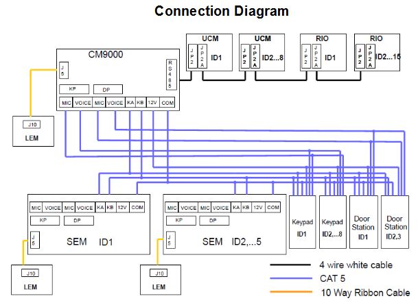 This can be downloaded from http://www.cytech.biz/hookup_diagram.html Another diagram, the Hookup diagram is included with Comfort on the lid of the enclosure. This can be downloaded from http://www.cytech.biz/hookup_diagram.html  .jpg) .png) Last edited on Tuesday Dec 2nd, 2014 05:27 pm by slychiu |
|||||||||
|
slychiu Administrator
|
See this post for instructions on End of Line Resistors http://www.comfortforums.com/forum127/4935.html |
|||||||||
|
slychiu Administrator
|
See "Common Problems Encountered" here http://www.comfortforums.com/forum16/4934.html Last edited on Friday Apr 7th, 2023 07:51 am by slychiu |
|||||||||