Posts: 6,044
Threads: 885
Joined: Apr 2006
Reputation:
3
05-19-2026, 07:57 AM
(This post was last modified: 05-19-2026, 09:53 AM by slychiu.)
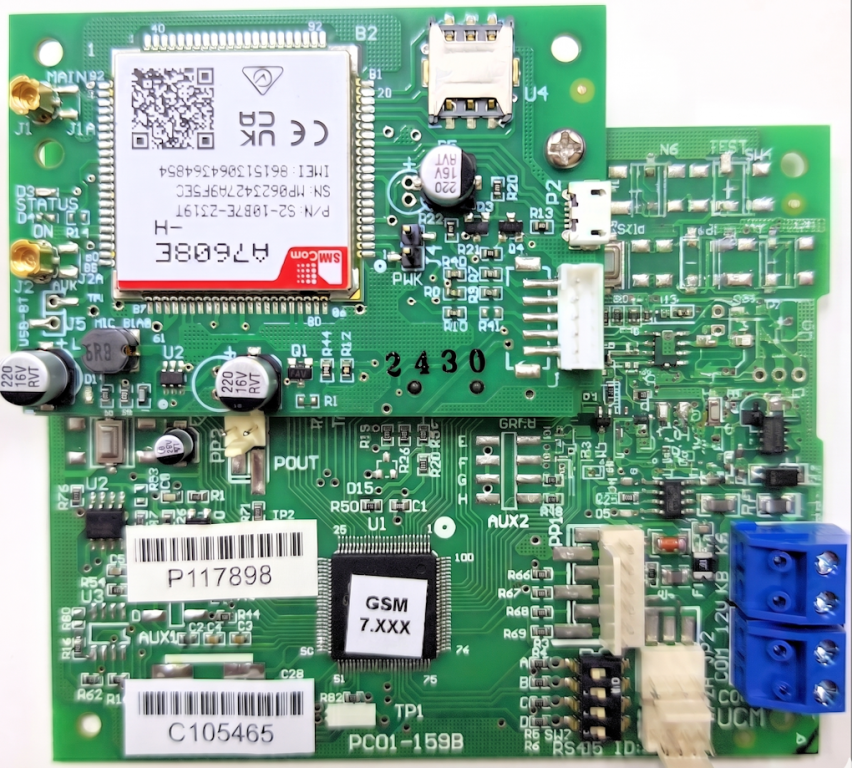 UCMA/4G7608 — 4G/LTE GSM Module for Cytech Comfort
Complete Installation, Setup and Configuration Guide
UCMA/4G7608 — 4G/LTE GSM Module for Cytech Comfort
Complete Installation, Setup and Configuration Guide
Introduction
The UCMA/4G7608 provides a 4G (LTE) cellular network connection to the Cytech Comfort alarm and home automation system. It acts as both a primary or backup communication path for alarm dialout, SMS notifications, and remote access by authorised users.
The UCMA/4G7608 consists of a baseboard with an ARM microcontroller and a pluggable 4G/LTE submodule (A7608). All configuration is done through Comfigurator — no special software or app is required.
The latest version of this manual can be downloaded from:
http://www.cytech.biz/product_details.php?item_id=588
Capabilities
- Acts as a backup for alarm dialout when the land line is faulty or cut. Can also be used as the primary dialler without a fixed telephone line.
- Allows the user to dial in via the GSM number to access Comfort voice menus remotely.
- Allows Comfort to report alarms to mobile phones via SMS — messages include time stamp, location identifier, alarm type, and zone or user name.
- Allows authorised mobile phones to send SMS commands to control appliances and the security system.
- Allows date and time synchronisation from Internet Time servers (SNTP).
- Supports Voice over LTE (VoLTE) for voice calls to and from Comfort.
Key Features
- Zone and Alarm Names (32 characters each) stored in UCMA/4G7608 EEPROM.
- 64 Customised messages can be sent by SMS.
- Help messages sent by SMS after receiving the "?" command.
- Query Security Mode and Control Status by SMS.
- Arm/Disarm Security System by SMS — replies with Security Mode status.
- Alarm SMS messages include time stamp and User Name for arm/disarm events.
- Each phone number has independent permissions for SMS Arm, SMS Disarm, and SMS Control.
- GSM Network Strength 0–10 and Signal-to-Noise (SINR) 0–10 displayed in Comfigurator status bar.
- Support for non-English character sets using UCS2.
Differences from UCM/4G
The older UCM/4G module (based on SIM7600) does not support Voice over LTE (VoLTE). It uses the 3G voice band for voice calls and will not be able to make voice calls on networks where 3G has been discontinued.
The UCMA/4G7608 supports VoLTE — voice calls are made entirely over the 4G/LTE network. It also uses a new ARM processor baseboard. The A7608 GSM submodule cannot be plugged into the original UCM/4G baseboard PCB.
Specifications
Code: PCB Size 108 x 88 mm
Power Supply 12V from Comfort — 50 mA (idle), 250 mA (transmit)
Operating Temp 0°C to 55°C
Relative Humidity < 95% RH non-condensing
SIM Card 3V / 1.8V — Nano-SIM format
EEPROM 24LC256 (256 Kbits) — stores all Comfigurator settings
Voice Calls Via 4G/LTE using VoLTE
Frequency Bands:
LTE-TDD: B38 / B40 / B41
LTE-FDD: B1 / B2 / B3 / B4 / B5 / B7 / B8 / B20 / B28 / B66
UMTS/HSPA+: B1 / B2 / B5 / B8
GSM/GPRS/EDGE: 850 / 900 / 1800 / 1900 MHz
Equipment Required
- Cytech Comfort CM9001 with firmware version 8.004 or higher.
- Comfigurator version 3.14.10 or above.
- UCMA/4G7608 Firmware 7.245 or above.
- A 4G (with VoLTE) Nano-SIM card.
What Is Included
- UCMA/4G7608 module with A7608 GSM submodule.
- 5-way audio cable (for J3 to J54 connection).
- 4-way RS485 cable (for JP2/2A connection to Comfort).
- 2 x antenna (with cable approximately 1 metre long).
Note: Package contents are subject to change without prior notice.
Contents of This Guide
- Post 1: Introduction, Key Features & Specifications (this post)
- Post 2: Hardware Overview — Connectors, ICs & LEDs
- Post 3: SIM Card, UCM ID Setting, Mounting & Setup
- Post 4: Configuration Part 1 — UCM Properties, Phone Numbers & Security
- Post 5: Configuration Part 2 — Names, Customised Messages, Control & Status Bar
- Post 6: SMS Messages from Comfort — Format, Examples & Restore Messages
- Post 7: SMS Commands to Comfort & Dialling In/Out
Posts: 6,044
Threads: 885
Joined: Apr 2006
Reputation:
3
05-19-2026, 08:15 AM
(This post was last modified: 05-19-2026, 08:32 AM by slychiu.)
Post 2: Hardware Overview — Connectors, ICs & LEDs
PCB Overview
The UCMA/4G7608 consists of two main parts: - Baseboard — contains the ARM microcontroller, RS485 interface, EEPROM, and power circuitry.
- GSM Submodule (A7608 / Daughterboard) — plugs into the baseboard. Contains the SIM card holder, antenna connectors, and 4G/LTE RF circuitry.

3.1 Baseboard Connectors
- JP3 — 12V/COM terminal block. Connect to 12V/COM on Comfort when JP2/2A is not used. Do not connect if JP2/2A is used.
- JP4 — KA/KB terminal block. Connect to KA/KB on Comfort when JP2/2A is not used. Do not connect if JP2/2A is used.
- JP2 and JP2A — 4-way headers (12V/COM/KA/KB). Either connector can be connected to Comfort's J6 RS485 header via the supplied cable for short-distance installations (less than 30 cm). For longer distances use JP3 and JP4 terminal blocks instead.
3.2 GSM Submodule (Daughterboard) Connectors
- J3 — 5-way connector for voice connection. Connect the 5-way audio cable from J3 to the J54 (GSM) connector on the Comfort CM9001.
- U4 — SIM card holder (Nano-SIM).
- USB (P2) — For future use only. Do not connect.
- J1, J2 — Antenna connectors. J1 is the primary antenna. Connect the GSM antenna to J1. J2 is not used.
3.3 ICs
- U1 — Microcontroller IC. The label on the IC shows the firmware version number (e.g. GSM 8.xxx).
- U5 — RS485 interface IC — handles RS485 bus communications with Comfort.
- U2 — 256 Kbit EEPROM 24LC256 — stores all Comfigurator settings.
4.1 LEDs on the Baseboard (UCM)
Code: D1 "RDY" Green Should be ON at all times during normal operation
D2 "BUSY1" Red Lit during initialisation or communications error
D3 "BUSY2" Red Lit when a call is in progress
D4 "ERR" Red Error indicator — lights when there is no network
D9 Red RS485 Transmit to Comfort
D10 Green RS485 Receive from Comfort
D9 and D10 should blink rapidly once RS485 communications between Comfort and the UCMA/4G7608 has been established.
4.2 LEDs on the GSM Submodule
Code: STATUS (D3) Red Flashes SLOWLY = 3G connection
Flashes FAST = LTE/4G connection
PWR Green Lit when power is supplied to the GSM submodule
4.3 Comfigurator Status Bar — GSM Signal Quality
When viewing the UCM/GSM Modules screen in Comfigurator, the status bar at the bottom shows real-time GSM connection quality. This information is not in the printed manual but is very useful for diagnosing signal issues.
Two separate values are displayed:
Network Strength (0–10) — indicates the received signal power level from the 4G/LTE tower. Higher is better.
Code: 0-2 Very weak or no signal
3-4 Weak / marginal
5-6 Fair
7-8 Good
9-10 Excellent
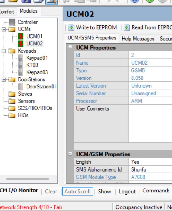 Status bar showing Network Strength 4/10 — Fair
Signal/Noise ratio — SINR (0–10)
Status bar showing Network Strength 4/10 — Fair
Signal/Noise ratio — SINR (0–10) — indicates how cleanly the tower signal can be distinguished from background noise and interference. A high Signal Strength with a low SINR means local interference is degrading the link quality.
Code: 0-2 Very poor — SMS delivery or voice calls may be affected
3-4 Weak — marginal performance
5-6 Fair — acceptable for SMS; voice calls may be affected
7-8 Good
9-10 Excellent
 Status bar showing Signal/Noise 2/10 — 4 dB Weak
Tip:
Status bar showing Signal/Noise 2/10 — 4 dB Weak
Tip: If either value is consistently low, try repositioning the antennas, or use a higher-gain or longer external antenna. If Network Strength is OK but SINR is low, the problem is local interference rather than distance from the tower. Contact Cytech for antenna advice.
To read the current values: click Get Status in the Comfigurator UCM Menu Bar.
Posts: 6,044
Threads: 885
Joined: Apr 2006
Reputation:
3
05-19-2026, 08:16 AM
(This post was last modified: 05-19-2026, 08:32 AM by slychiu.)
Post 3: SIM Card, UCM ID Setting, Mounting & Setup
5. SIM Card
A Nano-SIM card must be inserted into the SIM card holder (U4) on the GSM submodule. The SIM card may be prepaid or postpaid.
Note: A prepaid card does not notify the user when the remaining credit is depleted.
- The SIM card or mobile plan must allow sending and receiving of SMS messages.
- The SIM card's telephone number is used to dial in or send SMS commands to Comfort.
- To insert: push the card with the slanted corner going in first, gold contacts facing down.
- To remove: pull the card out in the opposite direction.
- Caller ID must be enabled on the SIM card to allow the UCMA/4G7608 to accept SMS commands.
- If using a prepaid SIM, activate it before use according to the carrier's instructions.
- Important: The SIM card must not be password-protected. Disable the PIN if one is set.
7. UCM ID Setting
Comfort supports up to 8 UCM modules on the RS485 bus. Each UCM must have a unique ID, set by the SW7 DIP switch on the UCMA/4G7608.
By convention, ID 1 is reserved for the UCM/USB, Wi-Fi, or ETH module. Set the UCMA/4G7608 to ID 2 or above so that RS485 communications failures can be detected and reported by Comfort.
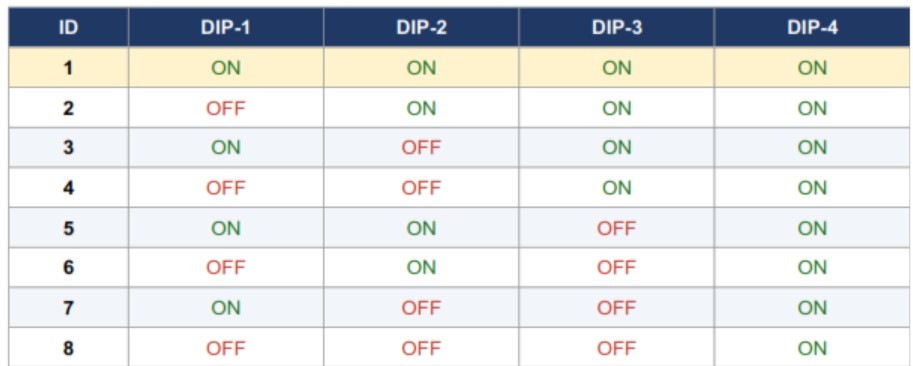 UCM ID DIP switch setting table as shown in Comfigurator
Important:
UCM ID DIP switch setting table as shown in Comfigurator
Important:- Do not use ID 1 for the UCMA/4G7608.
- Do not assign the same ID to two UCMs — this causes RS485 communications errors on the entire bus.
- Comfort's Modules and Settings screen must be programmed with the correct Number of UCMs.
- Press RESET on Comfort after changing the number of UCMs.
- Press SW1 (RESET) on the UCMA/4G7608 after changing its DIP switch ID. This does not change any Comfort parameters.
8. Mounting
Important: Do not mount the antennas inside a metal enclosure — this will severely degrade the GSM signal. If the UCMA/4G7608 is inside a metal enclosure, route the antenna cables to the outside.
Normally the UCMA/4G7608 is mounted in the same enclosure as Comfort because the 5-way audio cable (J3 to J54) is short. If it needs to be mounted elsewhere for better network coverage, use the ADM02 (Auxiliary Distribution Module) to extend the connection. Refer to the ADM02 manual for details.
9. Setup — Step by Step
Follow these steps in order before proceeding to Comfigurator configuration:
- Insert a Nano-SIM card into holder U4 on the submodule, slanted corner first, gold contacts facing down. Ensure PIN protection is disabled.
- Connect the GSM antenna to J1 on the submodule. J2 is not used.
- Set the UCM ID on SW7 according to the table above. Use ID 2 or above.
- Connect the 5-way audio cable from J3 on the UCMA/4G7608 to J54 (GSM) on the Comfort CM9001.
- Connect the 4-way RS485 cable from JP2 (or JP2A) on the UCMA/4G7608 to Comfort's J6 RS485 header. For distances greater than 30 cm, use JP3 and JP4 terminal blocks instead.
- Power on Comfort. The RDY LED (green) on the UCMA/4G7608 should turn on. BUSY1 LED will be lit while the module establishes its GSM network connection.
- Once the network is found, BUSY1 will go off. D9 and D10 will blink rapidly to confirm RS485 communication with Comfort.
- In Comfigurator, go to Modules → UCMs and scan for UCMs. Proceed to Post 4 for full configuration.
Note: If there is no network available, BUSY1 turns off and ERR turns on. The UCMA/4G7608 will retry the network connection every 10 seconds.
Note — DTMF Detection: If you have difficulty entering your user code during a dial-in or dial-out call, press each key for 1 second and allow 1 second between key presses.
Posts: 6,044
Threads: 885
Joined: Apr 2006
Reputation:
3
05-19-2026, 08:16 AM
(This post was last modified: 05-19-2026, 08:32 AM by slychiu.)
Post 4: Configuration Part 1 — UCM Properties, Security & Phone Numbers
All programming of the UCMA/4G7608 is done through Cytech Comfigurator (version 3.14.10 or above).
10.1 Scanning for UCMs
In Comfigurator, click the Modules tab → UCMs. Right-click on UCMs and select "Scan for UCMs" or "Scan for All Modules" to detect connected UCM devices.
If you are not connected to Comfort, select "Add UCM" and choose the type as GSM4.
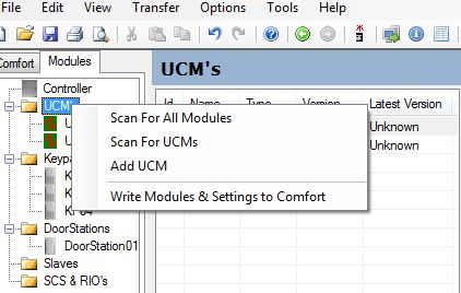 Right-click on UCMs to scan — or Add UCM if offline
10.2 UCM Properties
Click on the UCM entry in the left pane (e.g. UCM02) to open the Properties screen.
UCM/GSM5 Properties screen in Comfigurator
- ID — The UCM/GSM ID (1 to 8), determined by the SW7 DIP switch.
- Type — GSM5 — identifies this as a UCMA/4G7608.
- Version — The currently installed UCMA/4G7608 firmware version.
- Latest Version — The current released firmware (shown when connected to the Internet). Right-click the UCM entry and select "Check for Updates" to upgrade.
- Serial Number — Not applicable.
- English — Set to Yes for English. Set to No to allow SMS text in non-English languages.
- SMS Alphanumeric Id — Up to 32 characters — identifies the system in outgoing SMS messages. Example: "20:45 100 ABC Road – Intruder Alarm – Kitchen Movement"
- GSM Module Type — Identifies the GSM submodule hardware (A7608 for this product).
- Time Update from GSM — Interval in hours between SNTP time updates. First update occurs about 1 minute after initialisation. Set to 0 to disable.
- Time Zone — GMT offset in hours for your location.
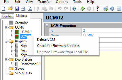 Right-click the UCM entry to check for firmware updates
10.3 Help Messages
The Help Messages screen shows the SMS help text sent to a mobile phone when it sends "?" or "1" to the UCMA/4G7608. This text can be edited to support other languages.
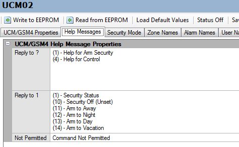 Help Messages configuration screen
10.4 Security Mode
The "Security Mode Names" field defines the text used in security mode SMS messages. The default names (Off, Away, Night, Day, Vacation) can be changed for other languages.
The Phone Numbers field in this tab allows entry of up to 2 mobile phone numbers that will be notified when a GSM RS485 Communications Failure occurs — i.e. when Comfort loses RS485 communication with the UCMA/4G7608.
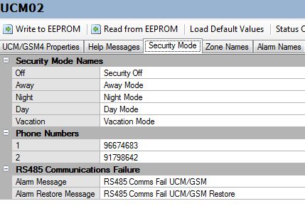 Security Mode names and communications failure phone numbers
10.5 Phone Numbers
Go to Security → Phone Numbers to program phone numbers for SMS dialout and voice calls. Click on a Phone Number entry to open its properties.
 Phone Number Properties — type, number, and SMS permissions
- Phone Type — Select SMS for SMS-only phones, or Voice for voice-only phones. A phone can appear in two entries — once as Voice and once as SMS.
- Phone Number — Enter in international format if required.
- Allow SMS Control — enables the phone to send Home Control SMS commands.
- Allow SMS Arm — enables the phone to arm the security system by SMS.
- Allow SMS Disarm — enables the phone to disarm the security system by SMS.
Note: "SMS" appears as a Phone Type option only when a UCMA/4G7608 or UCM/GSM module is configured as one of the UCMs.
 Phone numbers list showing SMS and Voice types
Posts: 6,044
Threads: 885
Joined: Apr 2006
Reputation:
3
05-19-2026, 08:17 AM
(This post was last modified: 05-19-2026, 08:32 AM by slychiu.)
Post 5: Configuration Part 2 — Names, Customised Messages, Control & Status Bar
10.6 Zone Names
This screen shows zone text initially copied from Comfort's Zone assignments. You can assign different text for GSM SMS messages (up to 32 characters) and add support for other languages. Zone names appear in outgoing SMS alarm messages.
.jpg) Zone Names — edit zone text for SMS messages
Zone Names — edit zone text for SMS messages
10.7 Alarm Names
These are the Alarm Names used in outgoing SMS messages, initially copied from Comfort's Alarm Types. Names can be up to 32 characters and edited for other languages. Default names should generally be left unchanged to maintain consistency across systems.
.jpg) Alarm Names — alarm type text used in SMS messages
Alarm Names — alarm type text used in SMS messages
10.8 User Names
User names are copied from Comfort (16 characters maximum). They appear in SMS messages for arm/disarm events — e.g. "System Armed by Mr. Big".
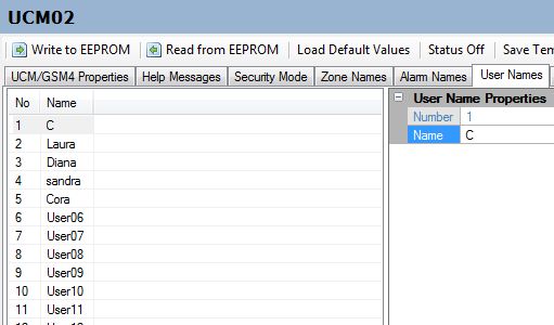 User Names screen
10.9 Customised Messages
Up to 64 customised messages can be programmed to be sent by SMS. To trigger one, use the Comfort action "Send SMS Message" in Comfort programming, then select the Phone Number and Message number.
 Customised Messages — text for up to 64 programmable SMS messages
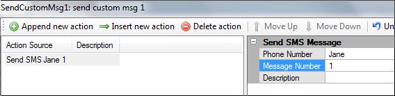 Comfort action — Send SMS Message to a programmed phone number
Important:
Comfort action — Send SMS Message to a programmed phone number
Important: The number of customised messages that can be sent at one time is currently limited to 3. If more than 3 messages are needed simultaneously, use a Timer Delay between groups of messages.
10.10 Control
This screen shows the text for Comfort's Home Control groups and menu items, initially copied from Comfort. Edit names to suit your installation or to shorten them to fit within the 160-character SMS limit.
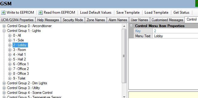 Control menu — group and item names for SMS control commands
Important:
Control menu — group and item names for SMS control commands
Important: Every Control Group MUST have a name assigned for the SMS Control menu commands (4x) to work. If Group 0 has no name, control commands will not respond.
10.11 Menu Bar
The menu bar at the top of each UCM configuration screen provides:
 Comfigurator UCM menu bar
- Write to EEPROM — Saves all configuration to the UCMA/4G7608's U2 EEPROM. May take several minutes. Insert the SIM card before writing.
- Read from EEPROM — Reads the current GSM4 configuration from EEPROM and populates all configuration pages.
- Load Default Values — Copies default values from Comfort and clears the current GSM4 configuration. Use as a starting point for a new installation.
- Save Template — Saves the GSM4 configuration as a .ugtx file for reuse.
- Load Template — Loads a previously saved .ugtx configuration file.
- Get Status — Reads the current GSM status from the UCMA/4G7608 — including the Network Strength and Signal/Noise values described below.
Understanding the GSM Status Bar (Additional Information)
This section contains information not in the printed manual.
When you click Get Status, or whenever the UCM/GSM screen is open, the bottom-left status bar shows two real-time quality indicators for the 4G/LTE connection:
Network Strength — 0 to 10
The received signal level from the 4G/LTE tower (equivalent to RSSI/RSRP). Think of it like the bars on your mobile phone — higher means stronger signal from the tower.
Network Strength 4/10 — Fair
Signal/Noise ratio (SINR) — 0 to 10
The Signal-to-Noise Ratio of the 4G/LTE connection. It measures how clearly the tower signal stands out from background noise and interference. You can have a strong signal but poor SINR if there is significant local interference (e.g. nearby electrical equipment, metal surfaces reflecting the signal).
Signal/Noise 2/10 — 4 dB Weak
Code: Reading Strength SINR
0-2 No or very weak signal Very high interference
3-4 Weak / marginal High noise, poor quality
5-6 Fair Moderate — SMS OK, voice marginal
7-8 Good Low noise
9-10 Excellent Very clean signal
- Move antennas higher or outside the metal enclosure.
- Use a longer coaxial antenna cable to position the antenna near a window.
- Try a directional or higher-gain external antenna in difficult locations.
- If Network Strength is OK but SINR is low, the problem is local interference, not distance from the tower.
- Contact Cytech for advice on antenna selection and placement.
Posts: 6,044
Threads: 885
Joined: Apr 2006
Reputation:
3
05-19-2026, 08:18 AM
(This post was last modified: 05-19-2026, 08:32 AM by slychiu.)
Post 6: SMS Messages from Comfort — Format, Examples, Restore & Dial In/Out
11.1 SMS Buffer
Comfort maintains a buffer of 16 events for SMS reporting, to handle multiple alarms occurring simultaneously. If the buffer fills up (because network problems have prevented sending), new events will not be added and will be lost. Messages not sent due to a temporary signal loss will be sent when the network is restored.
Important: If there is a communications failure between Comfort and the UCMA/4G7608 on the RS485 network, SMS messages will be lost and will not be recovered when communications is restored.
12.1 SMS Message Format
The format of outgoing SMS alarm messages from Comfort is:
Code: HH:MM XXXXXXXXXX - AlarmName - ZZ ZoneName
HH:MM Time of the event in 24-hour format
XXXXXXXXXX The SMS Alphanumeric Id (e.g. "100 ABC Road"), or
the 4-digit SMS Numeric Id — identifies the location
AlarmName From the Alarm Names tab (max 32 characters, single word)
ZZ ZoneName Zone number and zone name from the Zone Names tab
Code: Intruder alarm, zone 2 (Kitchen Window):
10:25 100 ABC Road - Intruder - 02 KitchenWindow
Power failure (no zone associated):
18:32 100 ABC Road - PowerFail - 01
RS485 communications failure from Keypad 2:
20:46 100 ABC Road - RS485Comms - Keypad 2
Low battery on Slave 1:
11:19 100 ABC Road - LowBattery - SEM 1
When Trouble alarms (Power Failure, Low Battery, RS485 Comms) are restored, the word "Restore" is automatically appended. Reporting of Trouble alarm restores is always enabled and does not require programming.
Code: 04:03 100 ABC Road - PowerFail Restore
04:03 100 ABC Road - RS485Comms Restore
"Restore" is appended to a zone alarm message when the zone is restored, provided the Zone Restore field is enabled in Security → Zones/Inputs.
Code: 09:10 100 ABC Road - Intruder - 02 KitchenWindow Restore
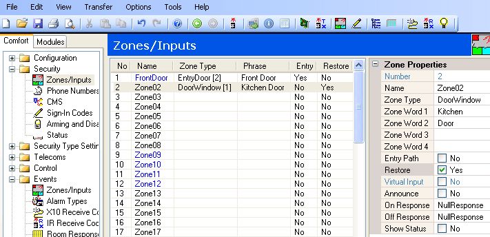 Security → Zones/Inputs — set Restore to Yes for zone restore reporting
Tip:
Security → Zones/Inputs — set Restore to Yes for zone restore reporting
Tip: Zone Restore is useful for smoke sensors, gas sensors, or industrial equipment where knowing when the sensor returns to normal is important. Do not enable it for PIR motion detectors or magnetic contacts — restore reporting would double the SMS traffic without useful purpose.
Note: Zone Restore can also be programmed using Engineer Menu 1, 4.
12.5 Armed / Disarmed Messages
When the system is armed or disarmed, SMS messages are sent to phones whose dialout is enabled for Alarm Type 19 (System Armed) or Alarm Type 17 (System Disarmed). Messages include the time, the SMS Alphanumeric Id, and the user name.
.png) .png) System Armed and System Disarmed SMS confirmation messages
System Armed and System Disarmed SMS confirmation messages
13. Dialling Out via GSM
Normally Comfort will not dial via GSM if a working fixed telephone line is connected. It will dial via GSM only when: - The telephone line has a low voltage — indicating a fault or disconnection ("Phone Trouble" alarm).
- A dial tone is not obtained — for example because an incoming caller is holding the line open.
If Comfort is connected to a PABX extension, it will not dial the PABX access digit when dialling via GSM. Configure this in Telecoms → Dialling.
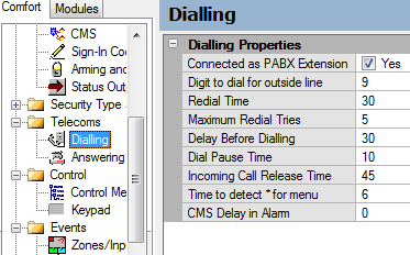 Telecoms → Dialling — PABX extension setting
When dialling to a Voice Phone via GSM, Comfort detects when the called party answers and immediately plays the alarm message — without waiting for the caller to say "hello" first.
When the telephone line is restored, subsequent dial-outs will revert to the fixed telephone line.
14. Dialling In via GSM
To access Comfort remotely, dial the telephone number of the SIM card installed in the UCMA/4G7608. Comfort will answer immediately (without waiting for the programmed number of rings) and prompt: "Please Sign In". Enter the user code as usual to access the system.
When the calling party ends the call, Comfort detects the disconnection immediately and returns to normal tasks. This is faster and more reliable than with a fixed telephone line, where Comfort must detect a busy tone to know the caller has hung up.
Posts: 6,044
Threads: 885
Joined: Apr 2006
Reputation:
3
05-19-2026, 08:18 AM
(This post was last modified: 05-19-2026, 08:32 AM by slychiu.)
Post 7: SMS Commands to Comfort — Control, Arm, Disarm & Help
Authorised mobile phones can send SMS commands to the UCMA/4G7608 to control Comfort, arm or disarm the security system, and query device status.
Basic Rules
- All commands must be enclosed in parentheses, e.g. (10).
- Only phone numbers programmed in Security → Phone Numbers as Voice or SMS type will be accepted. SMS from other numbers are ignored.
- Each phone's "Allow SMS Control", "Allow SMS Arm", and "Allow SMS Disarm" permissions must be set in Phone Number Properties before those commands will work.
- Any text outside the brackets is ignored — it can be used as a label or reminder.
15.1 Help Command
Send "?" or any unknown command to receive the help menu, which lists all available commands.
.png) Sending ? — the help reply shows available commands
Sending ? — the help reply shows available commands
15.2 Security Mode — Query and Commands
Send (1) to query the current security mode and receive the arming/disarming command menu.
Code: Command Action
------- ------------------------------------------
(1) Query current security mode and show menu
(10) Disarm (Security Off)
(11) Arm to Away mode
(12) Arm to Night mode
(13) Arm to Day mode
(14) Arm to Vacation mode
.png) .png) (10) — disarm reply and mode status | (11) — arm to Away confirmation
(10) — disarm reply and mode status | (11) — arm to Away confirmation
.jpg) Reply after arming to Night mode via SMS
Reply after arming to Night mode via SMS
If a phone does not have "Allow SMS Disarm" permission, the disarm command will be rejected:
 Command Not Permitted — phone lacks the required permission
15.3 Control Menu Commands
Send (4) to receive the Home Control menu listing available control groups.
.png) Reply to (4) — Home Control menu showing control groups
Reply to (4) — Home Control menu showing control groups
Send (4x) where x is the group number to see the items in that group. E.g. (41) for the Lights group:
.png) Reply to (41) — items in the Lights control group
Reply to (41) — items in the Lights control group
Send (4xy) to query the status of a specific device:
.png) Reply to (411) — shows device status and on/off commands
Reply to (411) — shows device status and on/off commands
Send (4xy0) to turn OFF and (4xy1) to turn ON. The UCMA/4G7608 replies with the new status:
.jpg) .jpg) Device turned OFF (4xy0) | Device turned ON (4xy1)
Note:
Device turned OFF (4xy0) | Device turned ON (4xy1)
Note: SMS messages are limited to 160 characters. If the Help or Control menu reply exceeds 160 characters, the message will be truncated. Shorten group and item names in the Control tab in Comfigurator to work around this.
Firmware Version History
The firmware version is shown in the Version field of the UCM Properties screen. To upgrade: right-click the UCM entry and select "Check for Updates".
- Firmware 8.xxx and above — required for UCMA/4G7608 (ARM processor baseboard).
Always download the latest firmware for the most current features and bug fixes.
Contact & Support
The latest manual can always be downloaded from http://www.cytech.biz/product_details.php?item_id=588
|


