Welcome, Guest
You have to register before you can post on our site.

Username
  

Password


Search Forums

(Advanced Search)

Latest Threads
Cbus to KNX translator - ...
Last Post: slychiu
54 minutes ago
System not announcing are...
Last Post: slychiu
1 hour ago
UCMA/Pi for Home Assistan...
Last Post: slychiu
1 hour ago
Trouble connecting
Last Post: Home
09-21-2026, 03:42 PM
Comfort Analog Input Grap...
Last Post: slychiu
09-12-2026, 08:31 AM
Comfort Server Manager 2
Last Post: slychiu
09-08-2026, 04:48 AM
Comfort App Converter Dow...
Last Post: slychiu
09-08-2026, 02:00 AM
Comfort Android App 2.1 t...
Last Post: slychiu
09-08-2026, 01:56 AM
Ucm velbus c9mmunicati8ns...
Last Post: wexfordman
09-05-2026, 11:29 PM
Custom Events
Last Post: Ingo
08-29-2026, 08:47 AM

Forum Statistics
» Members: 53,661,   » Latest member: PaulGordon,   » Forum threads: 5,214,   » Forum posts: 28,676,  
Full Statistics

  View Modes
Posted by: slychiu - 08-05-2018, 03:30 AM - Forum: How to Use Comfigurator - No Replies

Comfigurator 3.12.x has different View Modes to make it easier to use Comfigurator by hiding unneccesary programming screens that are not needed for the application


The view modes are

  • User Mode
  • Engineer Advanced Mode
  • Engineer Simplified Mode
  • EMS Mode
  • Automation Mode
Go to http://www.comfortforums.com/view_topic.php?id=4762&forum_id=20 for more info

Print this item

  Partitions in Comfort
Posted by: slychiu - 08-05-2018, 03:06 AM - Forum: FAQs - Technical - No Replies

This topic has been moved to http://www.comfortforums.com/forum125/4491.html

Print this item

  End of Line Resistors
Posted by: slychiu - 08-04-2018, 07:00 AM - Forum: Comfort Installation Instructions - Replies (2)

End of Line Resistors
The purpose of End Of Line (\"EOL\") Resistors for a security sensor is to allow the security system to be able to tell the difference between open and closed contacts (ie normal operation of the sensor) and open circuit and short circuit of the zone wiring (due to wiring faults or caused by someone cutting the wires).

EOL Resistor Values for Comfort
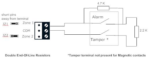
The two resistor values used in Comfort are 2.2 K ohms (red/red/red colour code) in series with the contact and 4.7K (yellow/purple/red colour code) ohms in parallel with the contact. (in older systems, 2.7K was used instead of 2.2K for the series resistor). The EOL resistors are provided in the accessories pack together with the battery leads.

Effect of Double EOL Resistors
If Double End-Of-Line  Resistors are connected and the Zone wires are cut or shorted together while the security system is NOT armed, a Zone trouble Alarm is reported for the zone, which will cause the keypad to beep fast for 10 seconds, and cause the keypad LCD to display the zone with the trouble condition. If the security system is armed and the zone trouble occurs, this will cause an immediate Intruder Alarm (as it could mean that someone has cut the alarm cable).


For CM9001 Comfigurator Zone Settings selects No EOL or Double EOL for each zone. No EOL means there are no EOL resistors connected to the zone. Double EOL means there should b2 2 EOL resistors on the zone


The Old CM9000 selects  EOL by jumper selection on JZ1 to JZ8 headers corresponding to each zone


Connections for No EOL Resistors are shown below. The zone shunt for each Zone JZ1, JZ2.. to JZ8 should be positioned on the 3 pin header so that it is closer to the Zone terminal block. The diagram shows 2 sensors in series. The Tamper connections are shown for PIRs and detectors. Tamper connections are usually not present for Magnetic door and window contacts.

If NO EOL is selected, Zone Trouble will not be detected. An open circuit and a short circuit on the  wiring will be no different from an Open Contact or Closed Contact, and will trigger an alarm accordingly when the system is  armed. Note that opening the Tamper connection has the same effect as cutting the zone wires.


Connections for Double EOL Resistors are shown below. The zone shunt for each Zone JZ1, JZ2.. to JZ8 should be positioned on the 3 pin header so that it is away from  the Zone terminal block. The Tamper connections are shown for PIRs and detectors. Tamper connections are usually not present for Magnetic door and window contacts.


Next

See this topic \"Programming the Security System\"
http://www.comfortforums.com/forum92/4059.html


Print this item

  Common Problems Encountered for newcomers
Posted by: slychiu - 08-04-2018, 06:21 AM - Forum: FAQs - Technical - Replies (2)

This is a list of common problems which may be encountered by newcomers when programming and testing Comfort

Tamper Alarm

When you turn on power on a new Comfort with a keypad connected, the Tamper alarm will be heard. This is due to the Tamper Input on the top edge of the Comfort Controller PCB left open. This is supposed to be connected to the contacts of a tamper switch to prevent unauthorised opening of the enclosure. To temporarily  disable this alarm, short it with a wire

Phone Trouble

After the system has been turned on for a minute, a Phone Trouble alarm will be heard.  The keypad will beep for 10 seconds and the LCD will show \"Phone Trouble\"This is because the telephone line has not been connected to the TEL IN terminal block on the top edge of the board.  The Telephone Line alarm occurs when the telephone line is disconnected or cut. Putting a short across the TEL IN terminal will NOT disable the alarm.  To temporarily disable the alarm (or permanently disable if a telephone line is not available), go to Alarms > Configuration Flags > Disable Line Cut


Acknowledge the alarm by entering the user code and # key on the Keypad. The Trouble alarm display will not be cleared if the alarm is not acknowledged
This also stops the siren sounds (if still sounding).

Zone Trouble
The Zone Trouble Alarm causes the keypad to beep for 10 seconds and the LCD to display \"Zone Trouble\". This is due to the wrong End of Line Resistor settings, or an external voltage on the ZoneCM9000 has End of Line Shunts for each of the 8 zones JZ1 to JZ8.

Acknowledge the alarm by entering the user code and # key on the Keypad. The Trouble alarm display will not be cleared if the alarm is not acknowledged
This also stops the siren sounds (if still sounding).

See this topic for information on End of Line Resistors
http://www.comfortforums.com/forum127/4935.html

Communications Failure Trouble Alarm

The Communications failure alarm causes the keypad to beep for 10 seconds and the Keypad to display \"Communications Failure\" (module name). This is caused by a module (keypad, UCM, IRIO etc which is supposed to be in the system not replying to polls from Comfort due to the wrong ID or disconnected See   http://www.comfortforums.com/forum16/69.html


Acknowledge the alarm by entering the user code and # key on the Keypad. The Trouble alarm display will not be cleared if the alarm is not acknowledged
This also stops the siren sounds (if still sounding).


Power Failure Trouble Alarm

The Power Failure alarm causes the keypad to beep for 10 seconds and the Keypad to display \"Power Fail\". This is caused by the loss of AC Power on the power point supplying Comfort. The Battery backup is providing backup power to Comfort. When the backup battery voltage is low, a Low Battery Alarm Will occur.
Acknowledge the alarm by entering the user code and # key on the Keypad. The Trouble alarm display will not be cleared if the alarm is not acknowledged
This also stops the siren sounds (if still sounding).

Low Battery Trouble Alarm
The Low Battery Trouble alarm causes the keypad to beep for 10 seconds and the Keypad to display \"Battery Warning\".
This is caused by a low battery voltage on the Battery backup to Comfort.

Acknowledge the alarm by entering the user code and # key on the Keypad. The Trouble alarm display will not be cleared if the alarm is not acknowledged
This also stops the siren sounds (if still sounding).

A daily Low battery Test is done every 24 hours. Comfort switches off the AC Mains power for 2 miinutes - if the Battery voltage drops to 11.5 Volts then the Low battery alarm is activated. The AC power is restored if this happens. When the user code is entered on the keypad, the LCD shows \"Battery Warning Restore\"
A manual Low battery check can be done anytime by pressing F,3,1 on the Keypad. This starts the 24 hours timer for the automatic daily battery check so that the next battery test will occur after 24 hours.

If the battery is very weak and cannot be charged , a Low Battery alarm can occur even if the AC power is on.


Arming Problems - Arm Failure

For arming to Away Mode, the occupants are required to leave the premises. That means that the Entry door (if closed) must be opened and closed within the Exit Time (30 seconds default). If the entry door is already open then it must be closed.After the door is closed, the system will arm to Away Mode and announce \"Away Mode\" on the keypad. If the Entry door is just left closed when arming to away then an Arm Failure alarm will occur. To clear it, disarm by entering the code (eg 12234#) on the keypad, and then arm againWhen arming to Night or Day mode, exit is not required.


Print this item

  Comfigurator 3.11.1 to 3.11.13
Posted by: slychiu - 07-29-2018, 01:18 PM - Forum: Comfigurator 3.x Old Versions (Archive) - Replies (5)

Comfigurator 3.11.1
Known Issues

  1. Writing to EEPROM for UCM/KNX writes  empty data, so the group addresses mapping is lost
  2. For Selective Read for any comfigurator item, if the referenced Response is not present in Comfigurator responses, then the response becomes Null. eg If Time Program references Response 100, and Comfigurator does not have this response, then the Time Program response becomes Null Response. Selective Read should be done only for information purposes. A Full Read from Comfort is needed to know the correct program in Comfort. (old bug)
  3. For Graph References, if there are any references to HIO and TSM modules (new unreleased modules), an un-handled exception is seen
  4. In IRIO, any input function after selecting  the Register Type (eg Couter, Flag), is not able to select the Register Number (Counter or Flag number). The workaround is to go to another Input or screen and come back to the input to select the Comfort register.
  5. For KT03 using Counters and Outputs, the Counter and Outputs Reference to KT03 is not shown in blue in the Counters page and Outputs page (old bug)
  6. When the cclx file wordlist does not match the vocabulary (Voice) in Comfort, logging in to Comfigurator will change the wordlist to the one in Comfort, but the words selected in Zones and Control menu are still the wrong wordlist and the words written to Comfort will be the worng  wordlist . To work around, the Wordlist in Comfigurator must be changed manually to the one on Comfort before doing a write to Comfort (old bug)
  7. Reading from Comfort does not read the Daylight Saving table into Comfigurator (in Sunrise/Sunset Times), although the Sunrise/sunset times are read. (old Bug)
  8. If  UCM/Cbus2 is present, all zones are referenced to UCM/Cbus2 because of the Cbus2 Physical Inputs, even though the Physiacl Inputs are not mapped to Cbus (old Bug)
  9. In Flags, if Check Status box is checked for a flag, the status is updated, but if the flag changes subsequently, the flag status in the centre pane is not updated until you go to another page and back, or uncheck and check the box (old bug)
Bugs Fixed
  1. Read from Comfort  removed all the Modules from the modules tab
  2. Register References for TSM and HIO were not shown. However now Graph References causes exception.
  3. For IRIO \"Show References\" did not include the \"Summer/Winter Flag Name\"
  4. For IRIO, ISM07 Relay I/O, Blinds DC had \"Unhandled exception\" error when clicking on Pulse width. After changing Pulse Width or Min Pulse Gap, the properties of the submodule cannot be changed.
  5. For IRIO, Read from IRIO always has Travel time = 254 seconds
  6. In Control Menu, after selecting Feedback Types = Output, Flags or Zones/Inputs, the words for 0 = Off and 1 = On are automatically entered. This works correctly now.
New Features
  1. Support for new UCM/KNX2 with enhanced KNX Interface. UCM/KNX2 is still being tested and is not released yet.
  2. Graph References hover remains on for 30 seconds (instead of 10 seconds) so it is easy to read the Responses.
  3. For IRIO, the control and feedback registers have been changed. Control/Feedback Register combines the main Control and Feedback register into one register so that the user does not need to specify a separate control register and feedback register if they are the same. 3 other control registers allow scenes
  4. For IRIO, each Submodule properties window shows a summary of the assigned Outputs and Inputs Functions without having to select each Output/Input to find out the Function assigned
  5. In the Control Menu, if Feedback Type = Output, Zones, or Flag is selected, the action Keys 0 and 1 are automatically entered as Off and On respectively. This saves time in programming the Control Menu especially for use in the Comfort app. In a future Comfort firmware upgrade, pressing the Off and On buttons wil automatically cause the Flag, Output to be turned on or off.  However the \"Off\" and \"On\" words  cannot be seen in the Control Menu unless you go to another page and come back to it.

Print this item

  Use of Timers for Delay
Posted by: slychiu - 07-29-2018, 02:23 AM - Forum: How to Use Comfigurator - No Replies

See this topic for how to use Timers

http://www.comfortforums.com/forum92/4062.html

Print this item

  How to use Timers for Delays
Posted by: slychiu - 07-29-2018, 02:22 AM - Forum: Automation Programming - No Replies

Refer to this topic in the forum for how to make use of Timers
http://www.comfortforums.com/forum92/4062.html

Print this item

  Comfort Firmware 7.142
Posted by: slychiu - 07-28-2018, 03:30 AM - Forum: Comfort Firmware - No Replies

Changes

  1. For Partitioned systems, a Partition is allowed to arm if other partitions are in alarm. In previous firmware, if any partition in alarm then the partition could not  be armed.
  2. Allow zone trouble for virtual input zone state = 2 or 3
  3. Fixed BUG from 7.140 Coice phone dial cleared by sms when alarm has voice phone and sms   
  4. KP06 volume is limited at 40 maximum to prevent damaged to the speaker

Print this item

  Upgrade to firmware UCM Not Found
Posted by: Ian - 07-27-2018, 03:12 PM - Forum: Firmware Upgrading Problems - Replies (18)

I have a Comfort II with 2 UCMs, UCM01 is ethernet UCM02 z-wave.
Today I upgraded the Controller Firmware to 7.142.
I was also adding a KP06a keypad, it is woring.

All seem to be OK until I noticed in Comfigurator UCM02 not polled. I have now tested the z-wave comms and it is not working.
I have done a reset via comfigurator as well as poweringdown and back up again. Has not helped.
Any suggestions?

Print this item

  Beta Release
Posted by: mattbrain - 07-24-2018, 10:38 AM - Forum: UCM/Pi - Replies (2)

Hi All

In the event you are interested in the Beta Release of the Production Build, and you haven\'t yet received an email to join, or aren\'t in the dedicated forum, please drop me a PM and i\'ll add you to it.

Thanks,

Matt

Print this item


Online Users
There are currently 1499 online users. » 1 Member(s) | 1492 Guest(s)
Applebot, Baidu, Bing, Facebook, Google, Yandex, Ingo

Powered By MyBB, © 2002-2026 Melroy van den Berg.